Micro:Bit - Light Strip
28 Nov 2021Last year I decided to spruce up my home office for Christmas a little bit, by using an LED light strip around the cupboard door that sits behind my desk. Rather than just using an off the shelf solution, I used a couple of BBC Micro:Bits (aka BBC MicroBit), to control the lighting effects and to provide a remote control. In this post I’m going to cover how I did this.
- The Components
- Wired Connections
- A Simple Lighting Example
- The NeoPixel Driver Library
- Micro:Bit Code for the Controller
- Adding a Remote Control Micro:Bit
- Summary
The Components
In this section I will run through the components I used to put together the lighting. You do not have to get the same things, or even all of the things listed below. It is just outlines what I have used - mostly things I had available from previous Micro:Bit projects with my kids.
BBC Micro:Bit
I am using two first generation Micro:Bit devices. Newer second generation devices could also be used, and with more options, you could take the project even further without requiring additional hardware to do so.
One of the Micro:Bits is used as the controller for the LED strip. The other Micro:Bit is optional. It is used as a remote for the controller Micro:Bit, and means that I can control the light strip n my office without having to turn around and fiddle with a Micro:Bit that’s tucked out of the way.
If you are going to use a second Micro:Bit as a remote control, do consider how you will power it. There are many options available, and I generally opt for the Kitronik MI:power board, or a AAA battery pack with power switch and JST connector.
LED Lighting Strip
The lighting strip I chose to use was a 5 metre long, 5 volt, WS2812B LED strip. In fact I got a water resistant one (rated IP67) just for a bit of added protection.
Any version should suffice, but the one I purchased was this one - CHINLY 5m 150leds WS2812B Individually addressable LED Strip Light SMD5050 RGB 150 Pixels Dream Color Waterproof IP67 Black PCB 5V DC
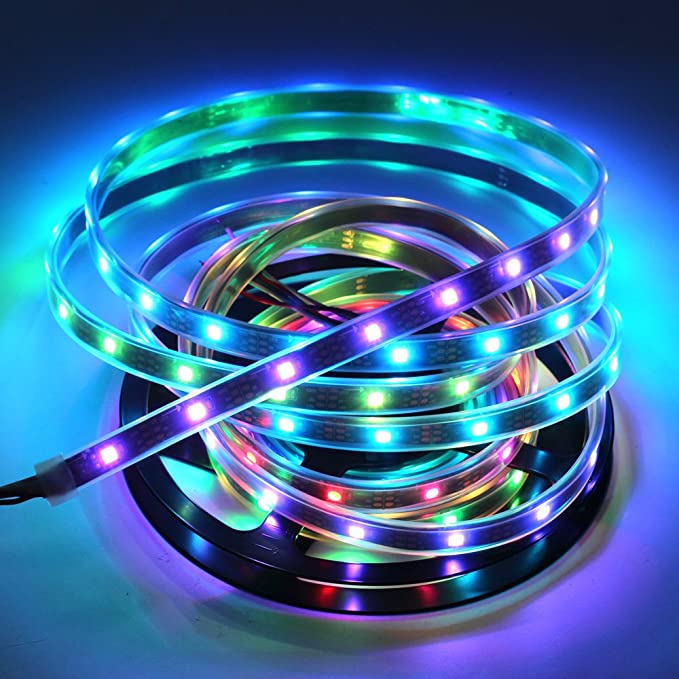
You can find the specification for WS2812B LED online, but you may also have heard them referred to as NeoPixel LED.
In the instructions for the strip, you should see something like the below that identifies each of the connections for three lines that drive the strip.

| Ref. | Colour | Purpose |
|---|---|---|
| GND | Black | The base level to measure other voltages from (0V). |
| DATA | Green | The line along which we will information to each LED. |
| DC5 | Red | The line for the deliver of a direct current of 5V. |
The instructions go on to note the following in terms of power requirements:
- 30 leds/m of light 5m/roll, recommend ≥10A 50W Power Supply.
- 60 leds/m of light 5m/roll, recommend ≥20A 100W Power Supply.
- 144 leds/m of light 1m/roll, recommend ≥10A 50W Power Supply.
This particular roll at 5m and 150 LED comes in at 30 LED per metre, and so requires a ≥10A 50W, power supply delivering 5V.
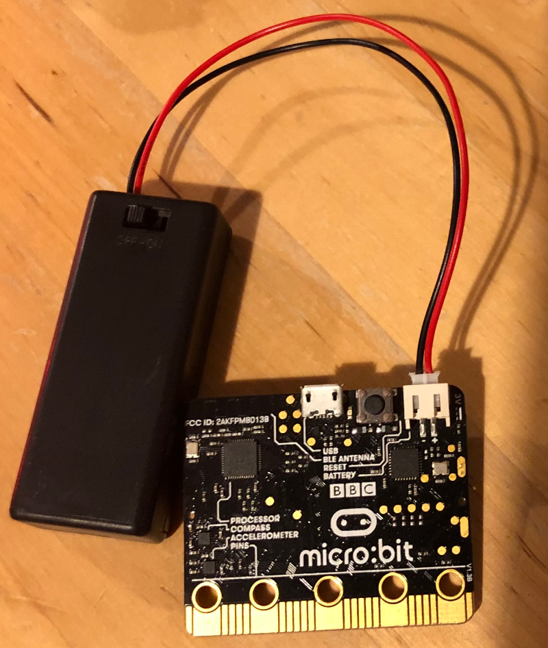
BBC Micro:Bit Connector, Breadboard and Jumper Wires
In terms of connecting the controller Micro:Bit to the LED strip, I knew I could do something with crocodile clips and get it working, but I had a few extra bits at my disposal that made this a lot easier. Specifically I had access to the Kitronik Inventor’s Kit for the BBC Micro:Bit, which included a breakout board for the Micro:Bit, a small electronics breadboard, and a variety of jumper wires.
Jumper wires and breadboards are easy to buy, and you can also pick up a variety of similar breakout connectors for the Micro:Bit (e.g. T-type), so there are a number of ways you could neatly connect a Micro:Bit up to a breadboard.
Because I was using a breadboard, I decided to use a breadboard terminal block to attach the power lines from the LED strip to the breadboard.
LED Lighting Power
To power my LED strip, I decided to use a USB hub. Given how bright NeoPixel LEDs are, I knew I was only going to run them at a fraction of their full brightness, and I knew I would be able to get away with something a little less.
I happened to have an old 7 port Bolse USB charging hub (5v, 12A : 5v x 12A = 60W), that I figured would be able to run the strip, and probably have enough juice to also run the controller Micro:Bit.
In terms of connecting the USB to the strip, I made an eBay purchase of a Breadboard Power Supply Module 3.3V 5V USB for Arduino Raspberry Pi Board MB102.
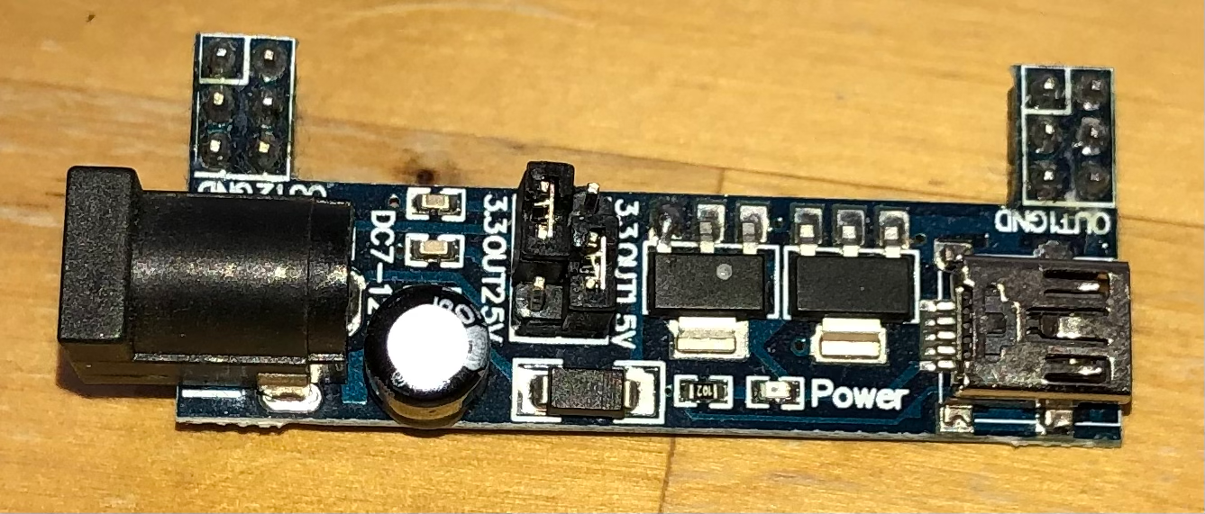
The adapter has two jumpers on it (little connectors that bridge between pins - in this case little plastic blocks with connector strips inside) that let you set the voltage output to the breadboard rails on each side. you can see them just to the right of the cylindrical capacitor in the photograph. I set them here so that the output on the left of this image is 3.3v and on the right it is 5v. You will want to set this for 5v for whichever side you power your LED strip from.
Wired Connections
While the wiring can look a little confusing in real life, the wiring is actually relatively straight forward.
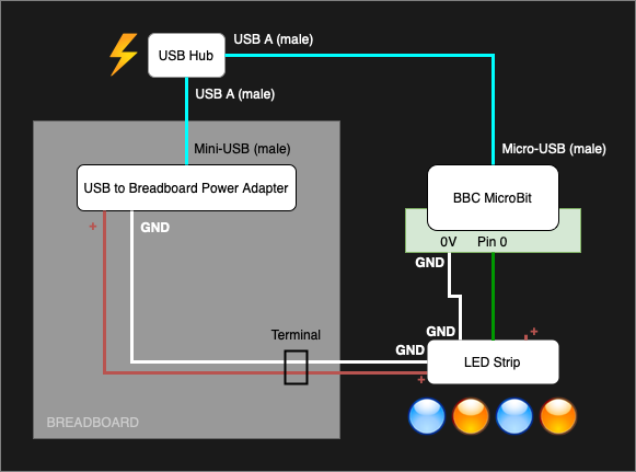
The USB hub powers the power adapter for the breadboard. The lines on the breadboard are connected to the LED strip (via male-male jumper wires and the terminal block I added for convenience).
The USB hub also powers the controller Micro:Bit. The Micro:Bit is plugged into a breakout board to make it easier to attach jumper wires from the Micro:Bit to the LED strip. The strip came with a connector attached to the other lines, which meant I could directly attack some (female to male) jumper wires.
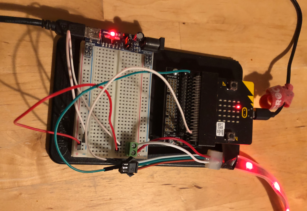
The resulting connections then looked like this.
A Simple Lighting Example
The following is a simple example to show some of the things you can do with your Micro:Bit controller, once everything is wired up. You can create and download your code at makecode.microbit.org. If you have never programmed a Micro::Bit before, then I would suggest having a look through the Micro:Bit support pages.
The NeoPixel Driver Library
Before you can control the LED strip from the Micro:Bit, the first thing you need to do is to select Advanced and then Extensions. From there, select the NeoPixel Driver, and this will include a library of code that allows the Micro:Bit to control (or drive) the LED strip.
![]()
Micro:Bit Code for the Controller
This is just a starter example for how you can construct the code, and it is based on allowing you to select several modes (each given a numeric ID). My own code for my set up is a little more extensive than what’s shown here in this example, but mainly because my kids always want to increasingly build in more and more lighting patterns and effects. Sometimes they come up with them, and sometimes they challenge me to see if I can get the lights to do what they describe.
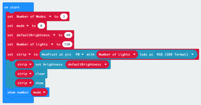
The starting code for running the LED strip looks like this:
![]()
It will give you three examples of lighting effects (plus lights off), which you can cycle through by pressing the A button on the controller Micro:Bit.
- Download: Christmas NeoPixel Strip Code
Variables
There are several variables set up in the code. These are really either constants that I wanted to separate out, or true variables that change during the operation of the program.
| Variable | Description |
|---|---|
colour |
Used to specify a randomly specified colour to be assigned to an LED in mode 2 |
defaultBrightness |
The brightness level (0-255)to run the NeoPixels at - they are very bright so you can get away with a relatively low setting and it will still be quite bright. |
index |
A counter variable used in loops |
mode |
Specifies which display of lights should be shown - mode 0 always turns the lights off |
Number of Lights |
The number of lights on the strip |
Number of Modes |
The number of light patterns available to be displayed |
strip |
A variable that represents the whole LED strip as an object |
On Start
The On Start section is run when the Micro:Bit first loads and so is the ideal place to initialise variables and settings.
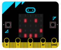
In the section I initialise the number of available modes (Number of Modes)to be three, set the initial mode to 0 (a fourth mode, setting lights off), set the defaultBrightness to 40 (out of 255), and the Number of Lights to be 150.
I also initialise strip to be a set of (150) NeoPixels on pin zero, setting its brightness and ensuring that it is showing nothing - in case it is being reset from a previous program run.
Finally, the current value of mode, which will always be 0 at this point, is displayed on the Micro:Bit’s LED matrix.
Button A
The On Button A Pressed section is triggered when the A button is pressed on the Micro:Bit. It is used to increment the mode variable and set-up different sets of lighting. It begins by clearing the strip, then setting up what should be displayed next, and finally to display the updated lighting effect.
| Mode | Description |
|---|---|
| 0 | Lights off |
| 1 | All lights white |
| 2 | Randomly set each light as red or green (50:50) |
| 3 | Set the lights to be a range of colours from red to blue (rainbow) |
Modes 2 and 3 will also be modified on an ongoing basis as covered in the next section.

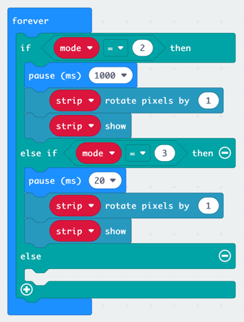
Forever
The Forever section runs constantly once the On Start section has run. In this section I have added a couple of entries to take action when the mode is set to 2 or 3. In each case, the NeoPixels on the LED strip are rotated by one step (the colour of the last LED becoming the colour of the first). The only difference between the two is the delay between rotations.
Adding a Remote Control Micro:Bit
I mentioned at the start that we could make use of two Micro:Bits, using a second as a remote control I found this useful as it was otherwise cumbersome to change the lighting from my desk because of where I was “hiding” the controller Micro:Bit. To enable a remote control, we can take advantage of the Micro:Bit’s radio functionality.
BBC Micro:Bits support short range (up to about 70m) radio communication, as well as Bluetooth via the same chip; but not simultaneously. We can use this to send and receive small packets of data between devices and then act on received data.
The approach for the remote is to be able to send an instruction from the remote to the controller to get it to switch to the next lighting pattern. We also want to be able to ask what the current lighting pattern is - we need to check this when we start up, because we are also going to have the controller update the remote with the current lighting pattern ID (mode), and so need to initialise it when we power up the remote Micro:Bit.
As a result, we not only need to create come new code for the remote, but also apply some amendments for the controller.
Radio Signals
Before we do that here is a quick summary of the radio signals we want to use.
| From | To | Name | Description |
|---|---|---|---|
| Controller | Remote | mode |
Sends the numeric ID for the current light pattern being displayed. |
| Remote | Controller | get |
Requests that the controller transmits the numeric ID for the current light pattern being displayed. |
| Remote | Controller | next |
Requests that the controller change to the next light pattern. |
Each of these signals is going to be sent as a name-value pair rather than as a string or a number. As well as enabling us sending the mode and distinguishing it easily from the other signals, this approach keeps all the processing in one place at each end, and also makes it easier to expand the radio functionality later on if you wish.
Controller Code Revisions
The code revisions might look considerable at first glance, but they are actually not all that extensive.
![]()
The first change we will look at is a new custom function called displayMode. This function shows the value of mode on the Micro:Bit LED matrix, and transmits a radio signal containing the ID of the current lighting pattern (mode).
![]()
The On Start block is almost the same as before. There are just a couple of additions. A set up for the radio group/channel to communicate on at the start, and a call to the function above in the displayMode function at the end.
![]()
Another new custom function is the setMode function. This is almost entirely taken from what was previously embedded in the On Button A Pressed section. The only real modification to what this does is the addition to call the displayMode function at the end. This function was separated out, just like the displayMode function, because it is going to be used in a couple of places.
![]()
As a result of this refactoring, the On Button A Pressed section is now just a call to the setMode function.
![]()
As well as changing the lighting pattern (mode) when the A button is pressed, we are also going to do it when we receive a radio signal requesting the controller Micro:Bit to do so. This is accomplished via the On Radio Received section. I am also going to redisplay and resend the value of mode when requested via a radio signal.
![]()
That’s the controller Micro:Bit set up, so next we need to set up the remote Micro:Bit.
Remote Code
The code for the remote is relatively small and simple.
![]()
In the On Start section, we set the radio group, initialise the mode variable (we keep this in sync across the two Micro:Bits), display it on the Micro:Bit’s LED matrix, and then send a signal to the controller Micro:Bit to ask for the current value of mode on that device.
In the On Radio Received section, we only have the mode signal to process, but we are going to check that this signal is the one being received, and we are going to take the value sent with it and set the mode variable to that value.
Finally, the On Button A Pressed sends a signal to the controller Micro:Bit to switch to the next lighting effect in the series.
Summary
Because this is built around using the BBC Micro:Bit, this makes a really good family project to do with any kids, or for any big kids. The instructions and code presented here should be enough to get you started, but there is a lot more fun to be had when you start looking at different types of lighting patterns, such as lights that twinkle, or that travel from one end to the other and then back. You can also use the v2 Micro:Bit speaker or attach one of your own to allow you to play tunes too. You can add functionality for the B button to cycle backwards or immediately reset the mode to zero when you clap using a microphone.
The possibilities are only really limited by your imagination, and the building is more than half the fun. Enjoy!