Home Assistant Enhanced Desk Clock
29 Oct 2023Like many people, my day job involves a PC. A PC that is relatively locked down in terms of what I can and cannot do to it. One of the things I miss from having more access is the option to set the clock in the Windows Taskbar to show the time including seconds - a registry setting can enable this. This may sound odd, but given 30 seconds I can nip out of my home office and grab a cold drink for example; I find knowing where in a minute I am when I am due in a call to be really useful as I detest being late.
This situation was recently compounded by a problem I’ve been having with my system clock slipping out of time. I can correct it at the BIOS, but my NTP access for automatically setting appears to be linked to another issue my laptop has been experiencing. The solution is simple - I just needed a little physical clock for my desk I could pop next to my Taskbar. I could not find any that I liked, so I decided it would be a nice little project to create one and maybe add a few features.
Home Assistant and ESPHome
Having been getting into Home Assistant recently and having been experimenting with the related ESPHome project I figured that I could create something useful using some ESP32 hardware with a screen and my existing Home Assistant set-up.
Home Assistant provides my home automation hub and being able to tie my clock into that I figured would give me extra power and options as the hub can collate and provide information to the clock if needed, as well as being something the clock could communicate with to trigger other actions.
ESPHome is a project to allow you to build controlling software for ESP32 microcontrollers using configuration files and associated resources. It sounds daunting at first, and while it can be used to build wonderfully sophisticated systems, with only a little effort, you can build much simpler ones. For my purposes, this was definitely towards the bottom end of this scale.
With a platform selected, I just needed to find some appropriate ESP32 hardware.
Selecting the ESP32 Device
Fortunately, with only about an hour or so of research and reading up on various options I was able to decide upon a particular ESP32 board for my desk clock. The LILYGO® T-Display-S3 ESP32-S3 Development Board ST7789. It has a 1.9” LCD screen as well as Wifi and Bluetooth. I managed to pick it up for about £20 on Ali Express, including a case, but you can pick it up cheaper without the case, and you can of course choose different ESP32 devices entirely - there are several that could fulfil the basic requirements I had.
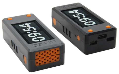
The board itself is 6.2 cm x 2.6 cm x 1 cm, but with the pins soldered on (I got them pre-soldered with the case), the case accounts for the extra depth and the entire module comes in at 7 cm x 3 cm x 2 cm. It is also powered via USB C, but being located on my desk and it being a very low power device, I simply used a USB A to USB C cable to provide power from the hub I dock my PC to.
If you are particularly technically inclined you can find lots of useful information about the module in a LILYGO® GitHub repository for the T-Display-S3 devices.
Configuration
I already had the ESPHome integration installed in Home Assistant, so if you want to follow along, you will need to ensure that you have that installed. Fortunately ESPHome has a nice little walk through for getting started.
With ESPHome in place on Home Assistant and an initial install of ESPHome firmware on the LILYGO® module, we just need to build up our configuration in the YAML configuration file for the device.
TIP: Don’t forget (like I almost always do) to hold the BOOT button when flashing the device to set the device mode to receive the new firmware.
I’ll step through the various sections to explain what they are doing and how you might want to modify them, then at the end we’ll put it all together so you have one source to copy and paste into your actual configuration and start modifying.
Substitutions
The first section of the configuration I have is for substitutions. I’m not overly creative for my naming and so I called my clock “ESP Desk Clock”, and set a couple of simple names (no spaces) to use throughout the configuration. You can change these to whatever you wish, and then in the key places through the rest of the configuration.
# Substitutions for use elsewhere in content
substitutions:
  device_name: espdeskclock
  friendly_name: ESPDESKCLOCK
ESPHome
The next section is the set-up of the ESPHome configuration for the device. Here, we pull in the substitutions from the previous section, and I also set an action to be carried out on boot up. I found the backlight for the T-Display to be overly bright for the lighting in the room I was working in. I wanted my clock to blend in to be the same sort of brightness as my PC’s main monitor. I found that a brightness of 60% was a good level for me to use. I would suggest experimenting to find the best level for your clock based on its placement.
We will come back to setting up the definition of the backlight in a later section.
# ESPHome
esphome:
  name: ${device_name}
  friendly_name: ${friendly_name}
  # On boot set the backlight to 60%
  on_boot:
    then:
      - light.turn_on:
          id: backlight
          brightness: 60%
You can take this further and have Home Assistant adjust the backlight level based on time of day, whether you have other lighting in the room on, what the weather is and if the window coverings are open, the light level in the room if you have a sensor for light levels, etc. This is the power and flexibility of hooking this device up to Home Assistant rather than simply programming the device using the Arduino IDE and running it standalone - which was my original idea on how I might build a personalised desk clock.
My lighting is fairly constant with my current set up, so I haven’t gone down this complex of a set-up, but I do automate the backlight and I’ll explain a little later what I am doing.
ESP32 Board
This section defines what type of board we are using to ESPHome. As you may have noted from the name of the module I selected, it is an S3, and if you read about the board yourself, you will also note that it supports the Arduino framework.
# ESP32 Board
esp32:
  board: esp32-s3-devkitc-1
  variant: esp32s3
  framework:
    type: arduino
Logging
During the development of the configuration, I found the logs were getting swamped with warnings from the display and yet I still needed to be able to check out errors that were occurring. The settings I found that worked best for this process are as follows.
# Enable logging
logger:
  level: DEBUG
  # Quieten the warnings about delays
  logs:
    tdisplays3.display: ERROR
    component: ERROR
This is effectively giving a good level of debugging and just quietening the display by only logging the errors and ignoring the warnings.
Display Preparation
This section is a critical piece of the puzzle and gave me a way to enable the display for use by ESPHome. It loads in some component code from a GitHub repository that defines to the ESPHome firmware how to interact with the display component.
# Load in component to allow use of the LCD screen
external_components:
  - source: github://landonr/lilygo-tdisplays3-esphome
    components: [tdisplays3]
Connectivity
Next come several sections that deal with connectivity. I am using the substitution entry defined at the start to name the fall back Wifi network, but more importantly, I have several ‘secrets’ being used.
# Over the air
ota:
  password: !secret ota_password

# Details of default Wifi and fallback hotspot
wifi:
  ssid: !secret wifi_ssid
  password: !secret wifi_password

  # Enable fallback hotspot (captive portal) in case wifi connection fails
  ap:
    ssid: ${device_name} Fallback Hotspot
    password: !secret ap_password

# No captive portal defined
captive_portal:

# Enable Home Assistant API
api:
  encryption:
    key: !secret api_encryption_key
It is good practice to put reused, sensitive information into a /conf/esphome/secrets.yaml file on your Home Assistant server. This works the same way the secrets.yaml file does for your Home Assistant configuration does.
To support the above, an example secrets.yaml file might look something like this.
# Your Wi-Fi SSID and password
wifi_ssid: "HomeNetwork"
wifi_password: "67TG^*Vh_0"

# Home Assistant
api_encryption_key: "hOXh7ul/fTtIyui+sBGvJxsmlwvWw0f/ChMOU99BBXX="
ota_password: 3fff3ffe000000a11111f00f5e0fffaa"

# Fallback hotspot
ap_password: "E-S_p.32-WIFIpwd"
You can probably copy most of these from your original firmware configuration that ESPHome generates when you connect and set-up your device, and any missing ones you can specify yourself, though for the API encryption key, I would suggest visiting the Native API Component page on the ESPHome website as it will give some useful background to using the API and will generate a suitable encryption key for you to use.
Time Source
While we could go out to the Internet and get the time from a time server, we can grab this from Home Assistant which has already done this for itself. Obviously having the correct time available is going to be a fundamental requirement for a desk clock.
# Get the time from home assistant
time:
  - platform: homeassistant
    id: ha_time
Backlight
Earlier I set the backlight to prime itself to 60% at device boot. Now we are going to define the backlight. If we review the pin diagram for the module, we can see that for the ST7789 (the type of display being used), there is an entry that says “LCD_BL 38”. As you may have guessed, this is noting that (general purpose input/output - GPIO) pin 38 is the data pin for the LCD display’s backlight.
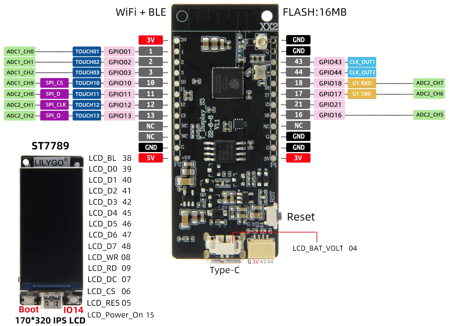
The first configuration section below sets pin 38 as an LED control (LEDC). This is used to set pulse-width modulation (PWM) signals to control the backlight.
Again, if you like the really technical stuff, EspressIf, the creators of ESP32 have a page on LEDC available.
The second section defines the backlight and associates it with the LEDC’s ID (led_pmw). It is this we interact with to control the backlight.
# Set pin for backlight
output:
  - platform: ledc
    pin: GPIO38
    id: ledc_pmw

# Set backlight controller
light:
  - platform: monochromatic
    output: ledc_pmw
    name: "Backlight"
    id: backlight
    restore_mode: ALWAYS_OFF
You do not need to understand in detail how all this works. It is easily enough just to know that when we give instructions to the backlight entity, the device knows that this will mean interacting with the physical LED backlight on pin 38.
IP Address
In this section I define a sensor for the device to make the IP address of the device available. In fact, this not only makes it available to the device, but also to Home Assistant. The IP address is assigned by my network’s DNS server to the device. It is not defined by the configuration.
# IP address text
text_sensor:
  - platform: wifi_info
    ip_address:
      name: ${device_name} IP Address
      id: host_ip
      entity_category: diagnostic
      icon: mdi:router-wireless
Fonts
The clock needs to be able to display text to display the time, so specifying a font to use is a requirement. For my clock, I also chose to display the date, and to help me quickly diagnose any network issues, the IP address.
Since I did not want each of these to be given equal prominence, I varied the sizes of the fonts. I did try mixing fonts of different typefaces, but I was unhappy with all my tests and eventually just decided on a very simple approach. However, I would encourage you to experiment with these as it is a great way to personalise your clock.
# Set fonts
font:
  - file: "gfonts://Roboto"
    id: ipfont
    size: 15
  - file: "gfonts://Roboto"
    id: datefont
    size: 25
  - file: "gfonts://Roboto"
    id: clockfont
    size: 60
From the above you can probably deduce which font is used for which purpose (look closely at the IDs). You may also note the (identical) file definitions all begin with “gfont://”. This is because I am using Google fonts.
You don’t have to use Google fonts. There are full details of how to specify and use fonts in the ESPHome documentation, but I think Google Fonts are the quickest to apply, and there are almost 1,600 fonts you can chose from at the time of writing. You can view the available Google fonts at fonts.google.com.
To use a Google font, just take the name from the last part of the Google font URL and prefix it with gfont://.
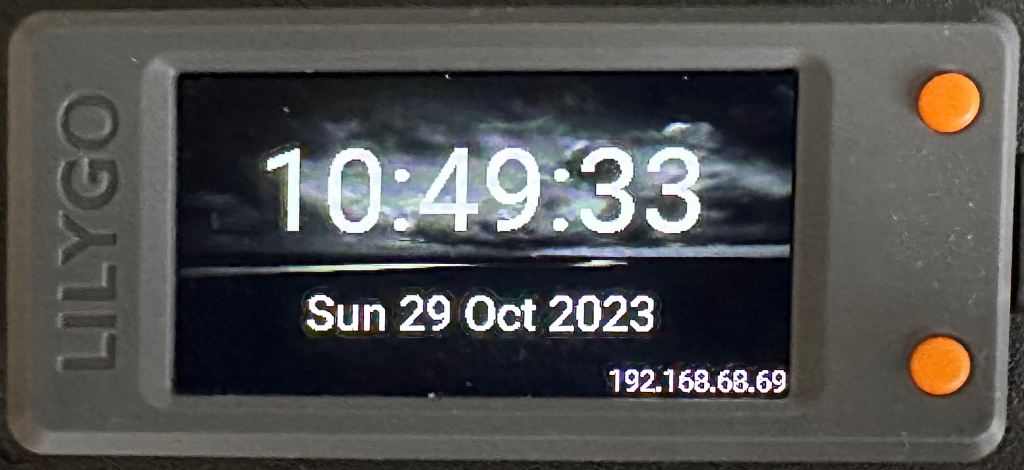
For example, the Roboto page is https://fonts.google.com/specimen/Roboto, and so the entry for the file property is gfonts://Roboto. Using that font gives text that looks like this.
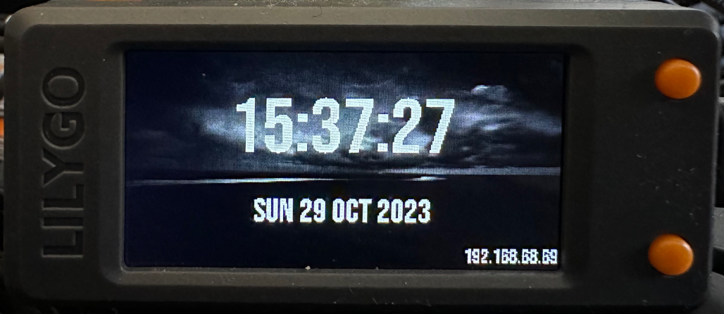
If instead we wanted to use Bebas Neue, the page for that is https://fonts.google.com/specimen/Bebas+Neue, and so the property would be set to gfonts://Bebas+Neue. The text then looks a little different because a different font is in use.
Background Image
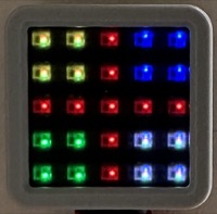
You may have noted on those previous images of the clock that the text was not on a black screen. The text is being overlaid on a screen that is showing an image.
The configuration to define (not display) the image is based on the details available on the ESPHome web site for image use in display components. It defines a file to be used for an image, an ID to reference it by, and a type (in this case a full colour image with no transparency - it is a colour JPEG image).
# Background image
image:
  - file: "sky.jpg"
    id: background_image
    type: RGB24
The file I used was this one:

While ESP32 supports resizing images, my display is such that I can set the size ahead of time, thus keeping the file size small and reducing the set-up processing. The image is 320 px x 170 px, which is the resolution of the ST7789 display component.
Naming the file sky.jpg (because it is a picture of a dark sky), I placed it in the /config/esphome/ directory. When ESPHome compiles the firmware, it will look in this directory for resources like image files, and pull it in.
While you can use any background image you like, keep in mind you want the text to stand out against it, so my recommendation is to have something the text will contrast well against.
Displaying Content
At last, we reach the section that puts the clock on the screen as we define the display.
The display is set to update every quarter second. The whole point of this device was to have a clock that displays seconds, so to ensure it is only up to a quarter second out, it is set to refresh at that interval. This accuracy and refresh rate is easily good enough for my use.
The display is also set to have a rotation of 90 degrees from origin. This lets me place the case with a long side down and the USB connection and buttons to my right as I look at the screen. If you want the buttons and connection on the other side, the rotation should be set to 180 instead.
In ESPHome, displays can be set to have multiple pages, with each page being a different thing to display. For now, all I was interested in was having a clock showing me the time and date, and so one page definition is sufficient. The page has a property defined called a lambda that looks quite “code-y”.
# 320 x 170 pixel display
display:
  - platform: tdisplays3
    id: lcd
    update_interval: 0.25s
    rotation: 90
    pages:
      - id: page1
        lambda: |-
          //Base colours
          auto White = Color(255, 255, 255);
          // Write background image
          it.image(0, 0, id(background_image));
          // Write clock
          it.printf(160, 60, id(clockfont), White, TextAlign::CENTER, id(ha_time).now().strftime("%H:%M:%S").c_str());
          //Write Date
          it.printf(160, 110, id(datefont), White, TextAlign::TOP_CENTER, id(ha_time).now().strftime("%a %d %b %Y").c_str());
          //Write IP Address
          it.printf(320,170, id(ipfont), White, TextAlign::BOTTOM_RIGHT, "%15s", id(host_ip).state.c_str());
The lambda is a definition of a self-contained set of code, written in C, that will do something. In this case it is going to lay out content on the screen, and I have commented it so you can see what it is doing.
//Base colours
auto White = Color(255, 255, 255);
// Write background image
it.image(0, 0, id(background_image));
// Write clock
it.printf(160, 60, id(clockfont), White, TextAlign::CENTER, id(ha_time).now().strftime("%H:%M:%S").c_str());
//Write Date
it.printf(160, 110, id(datefont), White, TextAlign::TOP_CENTER, id(ha_time).now().strftime("%a %d %b %Y").c_str());
//Write IP Address
it.printf(320,170, id(ipfont), White, TextAlign::BOTTOM_RIGHT, "%15s", id(host_ip).state.c_str());
The first line of code defines a colour, “White” as an RGB (Red/Green/Blue) equivalent.
The second line of code places the background image I set earlier onto the screen with no offset - i.e. at the screen origin (0, 0) at the top left corner.
The third line of code displays the time on the screen. I’ll jump around the parameters a little top describe this, but hopefully it will make more sense if I do it this way. The 160, 60 specifies a position on the screen using display coordinates. This is not the end, but rather the centre of the text to display as I have also used TextAlign::CENTER for how to place the text at those coordinates. The White of course refers to the text colour as defined on the first line, and the id(clockfont) specifies which font (the 60 pt Roboto) to display the text using.
The final part of the line is a little more complicated. It retrieves the value of the current time we get from Home Assistant, and formats it using a special formatting function and description. In this case it is a fairly obvious description - %H:%M:%S corresponding to hours, minutes and seconds (all two digit), in order, separated by colons. Something we are probably all familiar with for displaying a time, and what was shown in those earlier pictures. The final cstr() function call simply “casts” the output to be a printable string of characters.
The fourth and fifth lines are quite similar to the third. They vary the position, style, and the data being shown. One curiosity with a mention is the "%15s" entry in the final line for the IP address.
Note that the position specified in the final line is the very bottom right corner and that the output is set to be right aligned. The %15s indicates that the text being output should be 15 characters long with any padding to consist of spaces on the left of the text. This ensures that the IP address nestles up against that right-most edge regardless of the number of digits in the assigned IP address.
Buttons
To this point, everything has been output, but the LILYGO® T-Display-S3 also has a couple of buttons in addition to the reset button that we can make use of. Looking back to the earlier pin specification, these correspond to the ‘Boot’ and ‘IO14’ buttons shown on the diagram.
Taking into account the rotation of the screen, I labelled the IO14 button as the “Top Button”, and the Boot button as the “Bottom Button”. If you change your rotation to 180 to put the buttons on the other side, you will probably want to amend these names. In each case I’ve once again used the name from the substitution in naming the button.
# Push Buttons
# 90 degree screen rotation, so boot (GPIO0) is at the bottom.
binary_sensor:
  - platform: gpio
    pin:
      number: 14
      inverted: true
    name: ${friendly_name} Top Button
  - platform: gpio
    pin:
      number: 0
      inverted: true
    name: ${friendly_name} Bottom Button
While Boot was not given a specific pin number on the diagram, I took an educated guess it would be pin 0 and this proved to be true in my testing.
I have defined the buttons as binary sensors, and you can find out more about these on the ESPHome page about the Binary Sensor Component, and about the GPIO Binary Sensor class on its page.
I can use these buttons to trigger automations within Home Assistant making the desk clock a little smarter than average.
Full Configuration File
Below is what my configuration file looks like, so if you skipped to this section and did not bother reading the above, I would strongly advise you to go back and check out the details as you will no doubt want to personalise some of the configuration. At the very least you will want to upload a copy of a background image to the relevant folder.
# Substitutions for use elsewhere in content
substitutions:
  device_name: espdeskclock
  friendly_name: ESPDESKCLOCK

# ESPHome
esphome:
  name: ${device_name}
  friendly_name: ${friendly_name}
  # On boot set the backlight to 60%
  on_boot:
    then:
      - light.turn_on:
          id: backlight
          brightness: 60%

# ESP32 Board
esp32:
  board: esp32-s3-devkitc-1
  variant: esp32s3
  framework:
    type: arduino

# Enable logging
logger:
  level: DEBUG
  # Quieten the warnings about delays
  logs:
    tdisplays3.display: ERROR
    component: ERROR

# Load in component to allow use of the LCD screen
external_components:
  - source: github://landonr/lilygo-tdisplays3-esphome
    components: [tdisplays3]

# Over the air
ota:
  password: !secret ota_password

# Details of default Wifi and fallback hotspot
wifi:
  ssid: !secret wifi_ssid
  password: !secret wifi_password

  # Enable fallback hotspot (captive portal) in case wifi connection fails
  ap:
    ssid: ${device_name} Fallback Hotspot
    password: !secret ap_password

# No captive portal defined
captive_portal:

# Enable Home Assistant API
api:
  encryption:
    key: !secret api_encryption_key

# Get the time from home assistant
time:
  - platform: homeassistant
    id: ha_time

# Set pin for backlight
output:
  - platform: ledc
    pin: GPIO38
    id: ledc_pmw

# Set backlight controller
light:
  - platform: monochromatic
    output: ledc_pmw
    name: "Backlight"
    id: backlight
    restore_mode: ALWAYS_OFF

# IP address text
text_sensor:
  - platform: wifi_info
    ip_address:
      name: ${device_name} IP Address
      id: host_ip
      entity_category: diagnostic
      icon: mdi:router-wireless

# Set fonts
font:
  - file: "gfonts://Roboto"
    id: ipfont
    size: 15
  - file: "gfonts://Roboto"
    id: datefont
    size: 25
  - file: "gfonts://Roboto"
    id: clockfont
    size: 60

# Background image
image:
  - file: "sky.jpg"
    id: background_image
    type: RGB24

# 320 x 170 pixel display
display:
  - platform: tdisplays3
    id: lcd
    update_interval: 0.25s
    rotation: 90
    pages:
      - id: page1
        lambda: |-
          //Base colours
          auto White = Color(255, 255, 255);
          // Write background image
          it.image(0, 0, id(background_image));
          // Write clock
          it.printf(160, 60, id(clockfont), White, TextAlign::CENTER, id(ha_time).now().strftime("%H:%M:%S").c_str());
          //Write Date
          it.printf(160, 110, id(datefont), White, TextAlign::TOP_CENTER, id(ha_time).now().strftime("%a %d %b %Y").c_str());
          //Write IP Address
          it.printf(320,170, id(ipfont), White, TextAlign::BOTTOM_RIGHT, "%15s", id(host_ip).state.c_str());

# Push Buttons
# 90 degree screen rotation, so boot (GPIO0) is at the bottom.
binary_sensor:
  - platform: gpio
    pin:
      number: 14
      inverted: true
    name: ${friendly_name} Top Button
  - platform: gpio
    pin:
      number: 0
      inverted: true
    name: ${friendly_name} Bottom Button
Bringing it Home
As I noted earlier, I could have built something standalone for a clock - it is certainly possible using the Arduino IDE and the LILYGO® T-Display-S3. I have seen at least one example of this, and for anyone who is not using Home Assistant, I’d recommend that route.
The advantage for me of linking it up to Home Assistant was that it gave me a more integrated device. I am currently building out my smart home automations and having a tiny smart clock on my desk was a tempting prospect. It isn’t a super smart clock display like say a Amazon Echo Show, or a LaMetric Time , but it is smarter than it would be when standalone, and of course, for me it fits in a little corner under my monitor where my clock with just the hours and minutes displays in Windows.
To give you a bit of an idea how my clock is “smart”, I’ll give a couple of examples of things it does.
Read the Daily Weather in the Morning
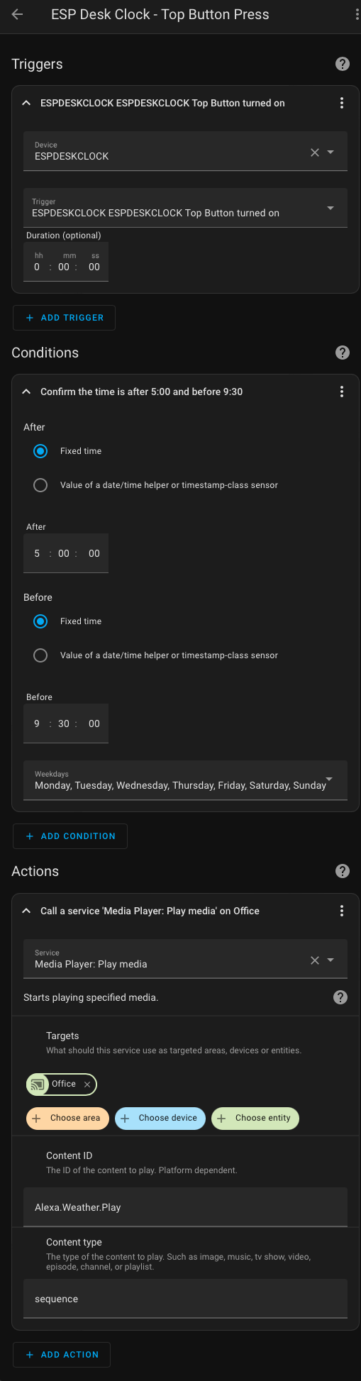
In my office I have an Amazon Echo, and I have set up an automation in Home Assistant whereby if it is between 05:00 and 09:30, it will instruct the Echo in the office to give me a local weather report.
The trigger is the press (on) of the top button on the device. The time is checked, and if it is the early part of the morning, a request is then sent to the Amazon Echo in the office to provide an audible weather report.
Show When Present
Throughout my home I have been setting up ESPresense devices - a way to track location of devices in the home using Bluetooth-based identification of devices. This allows me to know where devices such as individual family member’s phones are to be found.
My iPhone is one of the devices I have registered, and I generally have it with me no matter where I am in the house. Therefore I can roughly use the ESPresense state for this device to determine if I am in the office.
If I am in the office, then I can turn the backlight for the clock on, and if I am not in the office I can turn it off - saving a little bit of electricity and lowering the seemingly ever growing number of little LED light sources around my house.
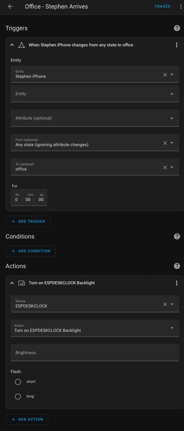
The backlight on automation triggers when the presence state for the iPhone changes to office (the name of the office location I have defined to the system). The action triggers an action for the ESP Desk Clock that turns on the backlight. Note that I can specify the level for the backlight here if I wish.
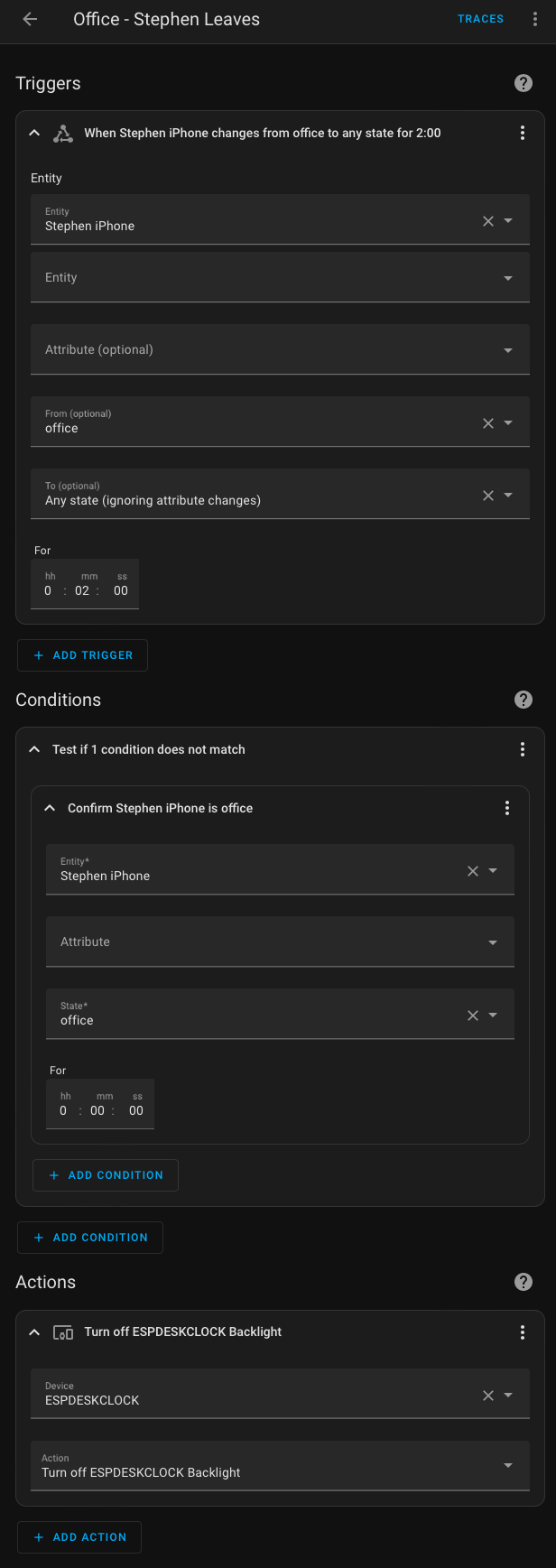
The backlight off automation triggers when the presence state for the iPhone changes from office. I found that if I did it immediately that occasionally the clock would blink off while I was in the room. The ESPresense unit I have in the office momentarily losing track of where the iPhone was. To counter that I added a two minute delay to the trigger after which it will check an additional condition to confirm that the iPhone is no longer in the office. This has given the automation better stability.
Conclusion
Hopefully this post has given you an idea about how to create a smart desk clock using Home Assistant, and why it might be worth linking an otherwise relatively simple clock into Home Assistant.
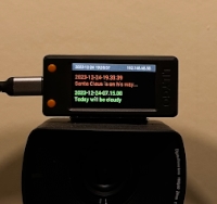
Of course, you may be thinking things like “hey, couldn’t we display messages with extra text overlays or more display pages?” The answer is “of course you can.” That in turn may lead you to wondering why I don’t do that. The answer is two-fold and quite simple. First of all, anything I really need to be made aware of is sent as a notification to my iPhone via the Home Assistant app notifications, or for more complex or more urgent ones to several devices via Pushover. Less time-critical updates, such as when it is warm enough in the office to warrant opening the window, when there is a Home Assistant update available, or when one of my children has reached the school bus stop actually get pushed to a second LILYGO® T-Display-S3 device located above my screen atop my web cam. I can retain my clock and direct any other information off to a dedicated second screen.
I plan to cover in detail the set-up of this other device in a subsequent blog post, but after reading this post you might even find you have a good idea of how to set about creating your own variation on this.
If you do create your own Home Assistant enhanced desk clock do let me know about what yours looks like and how you have enhanced it. The easiest way is probably to post it and tag me over on Mastodon where you can find me as @sylumer@mastodon.social.